30/03/22
Background
This project involved choosing a physical object, modelling the object to scale in Rhino3D, creating technical specification drawings for the modelled object, and finally rendering the model to digitally represent the original physical object.
Object Photos and Measurements
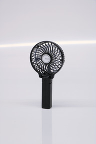
The object I chose to reverse engineer for this project is a mini desktop fan. I started by taking photos of the fan and measuring its outer dimensions before taking the cover off and measuring the interior components as well. The photos I took of the object are shown below:


My measurements of main components are shown in the following annotated sketches:


Modelling Process in Rhino
Handle
I started by modelling the basic shape of the handle using a rectangle and filleting the edges to the desired radius. I created these fillets by measuring the handle from corner to corner, making a circle with a diameter equal to this measurement, and filleting the rectangle edges to meet the outer edge of the circle. I also added a small "hinge" at the top of the handle using a cylinder and a triangular wedge.
Main Body of Fan
I shaped the main body of the fan from a simple sphere with the same diameter as the largest part of the fan. I used multiple Boolean Differences to cut away from this sphere and create the right shape of the fan with the right dimensions.

The next step was to create the front and back of the fan and add these parts to the main body I had created. I started by making two simple cylinders for the circles at the front and back of the fan. Next, I had to create the patterns of cuts that would form the "holes" in the front and back of the fan. I accomplished this by creating two circular planes, one for the front and one for the back, and then drawing an outline of one of the "holes" (i.e. the curve for the front of the fan and the wedge for the back). After turning these outlines into a surface, I used a Polar Array to essentially copy and paste these surfaces the correct number of times around the center of the circle. Finally, using a surface extrusion and a Boolean Difference, I cut these holes out of the main circle. Overall, this process formed the front and back pieces that I then moved onto the main body of the fan.
Finally, I had to create the holes around the outer surface of the main body. I did this by making a rectangle, using a Polar Array to copy it around the shell of the fan, and using a Boolean Difference to cut rectangular holes out of the shell.
Fan and Motor Components
To create the fan component, I first sketched a box with the maximum length and width of the two different fan pieces. I then created the outline of the fan using a curve tool and judging the shape of the pieces by eye. I made them slightly taller than their actual dimensions so that I could join them with the motor component, which I modelled using a cylinder.

I then turned these curves into surfaces, extruded them by a millimetre, used the Bend tool to curve them slightly and positioned them onto the cylinder. Using a Polar Array, I copied each piece three times around the centre of the cylinder to form the final shape of the fan.

Final Touches
To create a more refined model of the fan, I added 0.4mm fillets to every edge and changed the materials of the components. I used black opaque plastic for the handle, outer shell, back and front, and transparent white plastic for the fan and motor casing. The final model is shown in the image below.

Specification Drawing
The specification drawing for the model of the fan is shown below, featuring third angle projection drawings, an isometric drawing and exploded assembly drawings to show the different components and how they fit together.

You can also download the specification drawing here:
Final Render
I made two rendered images of the final model: the first one is an image of the assembled product and the second is an exploded image of the different main components to show how they fit in with one another.


Reflection
Throughout this project, I learned how the use of simple tools and patterns can help quickly and efficiently create 3D models to communicate ideas. Although my model doesn't accurately reflect every aspect of the handheld fan, it conveys the main concept in a clear manner by showing the main components and their sizes relative to each other. The use of tools such as Boolean Difference and Polar Array helped me significantly on this project since they allowed me to create the outer shell of the fan with relative ease. This project thus taught me the importance of mastering simple tools that can be used to make repeated patterns and shapes more efficiently than creating each object individually.
Still, if I were to continue working on this project, I would add more details to better communicate the final product. For example, I would consider adding the power button to the handle and the logo to the circle at the front of the fan. I would also find better tools to create a more accurate model of the clear fan pieces since I was forced to judge the shape of these by eye.
Overall, I'm proud of the way I was able to plan ahead and think about how each main component would be created, such as the shell being formed from a sphere. I'm also happy with the progress I've made in my ability to work with array tools, a skill that will be beneficial in future projects where patterns are required. Next time, I'll be sure to do more research into different Rhino modelling tools to find better ways of creating accurate curved objects.
Comments